hi all. Grin
this is my first post. sorry my bad English.
I will try to explain some consideration.
I do not want add or to place idea of Erfinder, but, the magnetism and electric
energy are one e different only in the frequency.
How thus?
If to catch one magneto or bar of steel carbon and to pass a small chain in
form of frequency and its polos to place bobbins connected in parallel, we
obtain to extract to power forces.
It is the same principle of the magneto turning around the bobbin, but what it
makes energy is how much the turn determines 60hz in cycles for second.
What he determines the generation of being able is the frequency and not it
mechanic moviment.
Then I could say that to be able electric it is a question of magnetic
frequency.
In the device of Erfinder, the magnetos are made use in perfect order of
frequency between polos N and S in second octava.
Erfinder congratulations.
Its simple and obvious thought opens the doors for new and intriguing key to
understand the universe and its functioning.
Hi again.
I imagine that coils tesla was a high-voltage resonante to stimulate currentes
in the circuit through high frequency(stress).
Tesla used this to generate its waves.
But the peoples think that he is for generating sparks.
The more stress more easy to break the substance.
I see a magneto as a powerful cell. He has all power there inside.
He has its state + and -. potential difference.
One impulse (High Voltage ressonant) opens the doors for a flow of power.
As Erfinder it says, magnetism and electric to power is one, requires only one
initial kick.
The sources are infinite. It is enough to look at for the universe. It by itself
works.
congratulations
I am not wild, only crazy
I am not wild, only crazy As my father already said.
Everything is a thought.
Before materializing itself it is an electromagnetic wave of the thought.
Hi all
1886 - Old motor rotating field AC
Another old
generator
Charlie_V
thank you for the patch.
I will redraw the graphs, before somebody gets confused.
I redraw a pictures.
Hi Charlie_V.
No. Photoshop.
I put layers and rebuild the paths with the tools.
Sorry my poor english.
Not expressing my thoughts correctly.
Hi there.
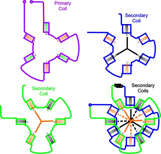
Well. + or - like this
1 - The Eddy currents induces the secondary.
2 - Secondarys looped in HV e HC.
3 - The devices basically is a transformer
Regards
Demystified!
The tesla secrets were anything anything else less than high frequencies to
create great static power!
Because?
Simple. Larger adhesion power and repulsion power.
Example: Try you to arrive close to a line of strength of high potency.!
Poor fellow, anger to fry and to be pulled with great strength.
The arrays of the reels are as a long one entrust coiled as only one.
Tesla was persisted in great potencies and frequencies.
He knew about that magnetic power.
It doesn't generate great currents, but he has the power of inducing them.
The arrays of the device is a transformer. That is:
With a little current 1/4 of the phase, it got a booster.
I know that I am annoying with that, more it excuses my terrible English.
I hope understand.
What tesla probably thought!
The current model is to generate of the font the great potentials and flux.
Tesla knew that the fonts were big and inexhaustible.
Of the mother earth the more far away from the stars of the universe.
The grid of energy distribution today, requests an expensive structure and of
great maintenance costs.
Tesla knew how to improve this.
That was ignored by the sands of the time.
The intellectual people of the time weren the theory of the electrons and they
didn't know deeply the magnetism observed by tesla.
Tesla knew of the magnetism of the magnetos and of the static of the high
frequencies.
High frequencies that were able transmitted for electromagnetic waves and
received by antennas.
Tesla wise to liberate the energy
No more for the moment.
Was forgetting.!
Really liberates the Free Energy.
Now my head this breeze for a new horizons.
http://www.borderlands.com/dollardandtesla.htm
Erfinder
Oh, yes.!
Chickens make eggs and eggs make more chickens.! Cheesy
Who did appear first ? Roll Eyes
The magnetism or Electricity? Here is the controversy hahaha. Undecided
Erfinder boy badly. Tongue
Please answer.
Hello all!!!
How is it that a magnetic field can be transformed in a field of high
(electrostatic) potential in a transformer without himself to be
electrostatic?
Being like this, I can affirm that: a transformer magnetic Iron works equal as a
not magnetic iron.
Is the difference, is one transformed by the origin strength and other it
already possesses his origin even?
ERFinder that would like that he answered me, please.!
How does a magnetic flow line produce electricity?
Doesn't produce anything. They are work in way the if they alternate in the
streams A.C., and they are direct + and - polarized in D.C.
Magnetism and electricity are same thing. Or I am wrong.
What is the nature of the flow line?
AC. Pulsed Alternate etc... or A.D. static or polarized
So that to produce or to induce electric effects this should also be
electric!
That made to remember of the pyramids of Egypt, with their sides of the faces
gone back to the magnetic north pole of the earth.
They seem to be capturing a field that comes of there. I know, that is
mysticism, more he reminded me something big.
Regards
The solid state Tesla pump DC
An device of the static corrent pump
Hi all
Look at this link. The good stuff.
http://etc.usf.edu/clipart/20100/20156/sepexcdynamo_20156.htm
Have many concept used in these devices.
Very, very simple to building.
By
Peoples.
Those waves Sinusoidal 90º are used to push pull or to excite the powers.
As wet string and you pass the fingers to remove the liquid. That is
important.
Waves of the strong sea play you for far.
They are as shock waves.
I didn't understand is: As H.V. Can he work in the place of inductive
currents?
I see HV of the device as an pulsating of the high frequencies. He will
reverberate as wave reflex!
With certainty it filters the waves and it impels again against.
Where does he work in that if the primary is power off?
I wait to have done understood inside of my thought.!
Regards
Peoples.
Those waves Sinusoidal 90º are used to push pull or to excite the powers.
As wet string and you pass the fingers to remove the liquid. That is important.
Waves of the strong sea play you for far.
They are as shock waves.
I didn't understand is: As H.V. Can he work in the place of inductive currents?
I see HV of the device as an pulsating of the high frequencies. He will
reverberate as wave reflex!
With certainty it filters the waves and it impels again against.
Where does he work in that if the primary is power off?
I wait to have done understood inside of my thought.!
Regards
Hi
2 links good
http://www.kz1300.com/ecklin/
http://www.mullerpower.com/index2.php
Hi nat1971a
Great explanation! This much more in the path certain of the things.
Two questions that I still don't understand.
Are The vacuum formed in the equator lines of the coils? Which the lines flow
between rotor and the secondary?
Regards
Hi Erfinder
You mentioned that a magneto is an electrostatic element. Which is the strength
that pushes the individual magnets outside of the magneto?
Does the flow run of the south pole for the north or of the mid for the sides?
Magnetism would be the source then of that everything, best saying a vacuum.
Vacuous, it would be a strength that sucks the positive things and it repels the
negatives. Or it would be the opposite of that.!!
That vacuous one would be the main grid contained in every infinite of the
universe. That duality + and - in the magneto it would be the Electrostatic and
the vacuum the painting screen.
Each individual magnet that flows of that magneto would be the brushes where I
drawing my powers.
Example: To alter the south stream and later the north in a rocking frequency
would have an alternating current.
And does a direct continue strength how it would be then?
Thinking like this, could say that to infinite forms of composing a power.
Excuse my questions, but this painting in my mental screen, this wanting to flow
of the magnetos.
I wanting incorporate Leonnardo D'vinc that exists in me.
regards
Post by BushWacker:
Hello Guys,
I am attaching what I believe is going to be the final revision of the "HOPE
for the Future" Construction, Assembly, and Basic Information for those who have
the means and desire to experiment with this type of device. Please remember
that despite my many attempts to clarify that I am making no claims as of yet
that the HOPE Generator is a "Free Energy Technology" a number of people can't
seem to get that through there heads. ......Sterling, are you seeing this?
There have also been a few folks who talk as though I am hopping up and down
thinking that I'm going to power my car with this device......lol. Please
understand that the reason that I am offering this information is because I
believe this is a very interesting phenomenon, and I believe that we should be
able to use this knowledge to take things to an entirely new level of
development where we may very well be able to power our cars and/or homes with
something like this. It will probably look considerable different than the
original HOPE Unit/Generator but I predict that highly reactive piezo powders
will be introduced to the mix and that there will likely be some changes in the
shape of the cores in the future.
There is one person in this forum who despite the fact that he has really ticked
me off at times eg; (FreedomFuel), he is right about a whole lot of things
involving the reasons that the HOPE Generator does what it does. I believe that
he is also right on the money with his insights on rotating magnetic fields. I
would love to be able to afford to buy the materials necessary to take this
research to the level that I believe it has the potential to be taken to but
right now that doesn't look like its going to be possible. I can only HOPE that
I have finally been understood on the reasons why I felt that I should post my
findings on this forum. I also hope that people will stop telling others that I
am claiming that the current HOPE Generator is a free energy device. It does
appear to be according to the equipment that I have to measure the voltage and
amperage but if all of the conventional meters are correct then why is that
energy not able to light an incandecent bulb. It will create beautiful
bluish-purple streamers throughout the inside of the incandecent bulbs, but only
if one wire is used. It does nothing when both wires are hooked up.
A great many questions are going to be left unanswered until someone else with
money and the proper tools to investigate everything properly will either take a
look at what I already have developed or build their own and try to reproduce
exactly what I have done so far.
Agape All,
Jim
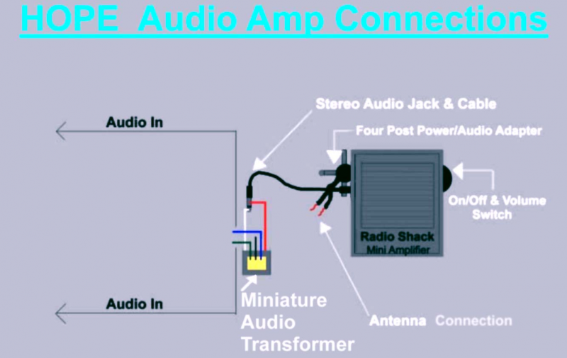
Post by BushWacker:
Hi Everyone,
Check the attached file for a schematic of how the Radio Shack "Mini
Ampliefier" and "Miniature Audio Transformer" are connected to a HOPE Unit in
order to create self tuning optimum feedback resonance for most builds. There
have only been about 3 instances where certain HOPE Models generated higher AC
potential without the miniature audio transformer. Therefore experimenters are
advised to test their HOPE Units both with, and without the addition of the
miniature audio transformer.
This is the safest method of do any initial testing with a HOPE Generator to get
an idea of what a units conversion ratio's are like. However, remember that many
times a HOPE Generators efficiency ratings will climb according to how much
energy you feed it. I have built a numbr of models that when a certain critical
saturation point was reached on the input, the conversion factors went beyond
what anyone one believe unless they could see it for themselves. Also, with
certain builds it has proven possible to connect a HOPE Unit with a secondary
transformer. For each model where this has been the case a differing and
somewhat novel set of connections had to be made with each unique unit. When
just the right setup was found virtually any frequency could be used to generate
a great deal of AC Potential, and some units actually generated 2000 to 3000 VAC
with only moderate volume audio signals being used to induce such a reaction.
Until a few others start to take this research seriously though I am sure that I
must sound as though I am blowing smoke up everyone's wazoo's..
Cheers All,
Jim
Hi all. Cheesy
More discovered of ERFINDER.! It this disappeared.
Discovering more on tesla well clear so that let us can in moving them ahead.
I say: Tesla used high voltage in all its devices because?
Simple, to create electrecity a tension is basic.
It is the force that moves electric chains. A potential difference allows a flow. As in loading them of capacitors of tesla.
It made a polarization of loads to create a tension.
This tension allows to open the pipes current to flow it as in the water pipes.
This can be newness for did not you, more in such a way in a common magneto as in one cell, the basic one to create and to flow one current is to create a potential (tension).
This exactly a potential difference.
In the waves sine it is only possible with mechanical turn where they reach a minimum and a maximum between North Pole and south.
In cells is possible differences between used metals and acid the reactive elements type. Also for the capacitive elements as capacitors. As leiden Jar. Static power system. Oh!! Shocked
http://Regards
Hi all
I have innovations.!
I Replication Daniel McFarland's patents using the concepts administered here and worked well.
overcame the expected.
Sorry I not to have pictures to illustrate the experiences.
For the initial kicks of power I used a battery of 12v 7A of motorcycle.
The exciting is a coil electro-magnet. chickens make more chickens Grin. It´s real
Regards
Hello
My replication, about my point of view of the invention.

BushWacker
I want to suggest improvements in the device HOPE gen.
It is known that, a high speaker is a coils and a magnetic ring! Ok, without
innovations here.
But, it is used electric pulses to generate frequencies and to balance the
speker... Wow! And if to do the opposite.
A trafo in that ring with fine primary wire and secondary fat thread.
Quite so, the high speaker is the inverse of a generator, but to the opposite
that think, being a generator also.
As if it balances a coils inside of a magnetic field, it goes and it comes, and
that everybody knows what happens.
Gen. Hope is good overunit, however with a difference the most promising of
all.
Excuse my bad English.
Regards
Hello all
This morning I played with resonant frequencies of my walkman in the ring tpu
that I built.
I input whit 2 cells 1.5v, and collect 52v 1A in output.
When I decided to put a permanent magnetic ring in turn of the rings collectors
and...
Amaze, the readings jumped for more than 250v. with two cell my reader was
crazy.
I hope help
Regards
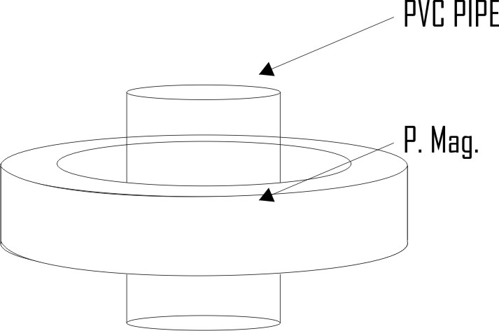
Hi ChrisC,
My TPU comprise in 24 turns medium wire and 1000 turns more fine wire in
parallel, mounted in pvc tube and isolated well isolated. I put permanent
magneto ring in turn of the tpu and reader jumped as crazy above the 250v.
TKS
chrisC
The initial reading was of 50v without the ring magnetic permenente.
But, when I put the ring permenente the things left my understanding.
The frequencies were of an old walkmam. The frequencies were of the sound that
run of the station tuned in place.
Yes, a transformer, high speaker, the primary vibrating in magnetic field,
secondary as collectors.
Tks
Hi
I believe with more amper and faster and broad pulses the thing begins to be
interesting.!
In it lives him.!
regards
Hi
The permanent magnetic ring on the outside of the pvc tube. The station was FM
stereo.
More thinks that is relevant.
Mine to think it is, the primary works as electromagnet of the pulses of the
sound frequency.
A diode rectifier was put in the outlet of the walkman for not having tension
return.
Tks
chrisC
Hi brnbrade,
Is this how your setup looked like?
Please confirm or post necessary changes.
73, Earl
Hi btentzer
I make little moving demonstrate my experiment concept.
Tks
Yes. Here anything of more for the moment.
The one that I wanted to show as the sound waves balances.
That inside of the one of my device also scale.
And it is known that a magnetic field varying in the time generates energy.
How yes, so fast the primary ones to balance the secondary ones they collect
more energy.
It is it that me leaning of that everything.
www.youtube.com
regards
btentzer
To begin with high big old speaker's magnet and pvc of 1/4 ".
tks
Hi All
As I had promised would post my results.
Love or hate. If hey want replicate and any question will be answered.
Think about my device with closed looped.
Enjoy
Regards

Yes Bruce.
Exactly.
Four of those in the tpu. Hummmmm!!!
Now only amper readings and to see the proofs.
I have hope to be the remaining part of the secret of SM.
Ps. The boot this output of the capacitor and not of the cells
Hi Bob
I will make the diagrams as possible. Only that you have some wait.
Something to consider.
I will test 2 cap. eletrolitic of the output for input. Like this closed loop in the circuit.
I will arrange a cicuit PWM with frequencies DC pulsed in input. The coils convert again for AC and reads the cap. eletrolitic again.
I will try this. Desire to rectify. Somebody can draw an outline for me...
60 watts 24V 2,5A
Hi all
Somebody please can draw a schematic of as one
mosfet could drain amper of the red wire.
Thank.
Hi Stefan
I draw the scheme of the my device this week.
I will do as possible.
I need scheme of the mosfets for drain the amps.
Regards
Hi bob
Tanks
I see the rectifying circuit
Regards
Draining which amps?
Yes, will test the behavior of the mosfet in circuit.
I will try in output the red wire of the device
My scheme
Hi all
No battery
Yes, the load reads ouver the 50v and decrease slowly, and persist 15v to 16v
I am testing all of the types possible of configurations. Attempts and mistakes. And in this it goes and it comes I saw strange things. The capacitors seem to hold the load for 12v to 16v. This dissipating energy.
EMdevices
Make the coils. You will prove for you same that works.
Hi all
I ask all that to want. Replicate and all can help that device develop.
The friends that possess oscilloscope and tools readers advanced, can help in
the walk.
Regards
Hi ,
How many turns of wire did you use ?
MacFarland mentions more wire more better the result.
In one posting was said 35 turns ?
In my device is 35 turns.
It can be more turns or less. I didn't play with this still.
Is this the big red wire ?
Thick red wire 35 turns.
How many turns does the fine wire have ?
Huh
Many thanks.
Hi Bruce
Tank for help me.
good jobs in replicate
If you need help. send PM
Tanks
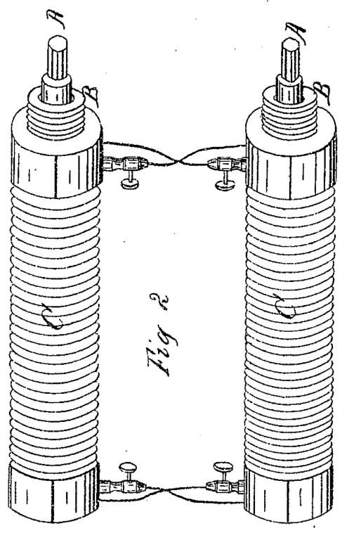
Words of McFarland
The mode of producing or starting the action in the helices consists in the use
of a steel or electromagnet, or a helix, around one of the helices, and causing
a secondary current in the inclosed helix by means of a battery current in the
outer one; the action then in either the simple or compound helices increases in
quantity to the maximum capacity of the wires to conduct with the existing
tension of the current. If, now, the circuit is broken the current instantly
ceases, and can only be restored by the same means that it was first produced;
hence to allow the use of the main circuit for common purposes I introduce a
rheostat or a resistance of any kind into the circuit, so that a small portion
of the current only will flow along the resistance, by which means the action in
the helices is feebly maintained when the main circuit is broken, and instantly
restored when it is closed to its full force. By this means the action becomes
in effect the same as the common battery currents, and may be used for similar
purposes. For the purpose of preventing the heating of the helices caused by the
intensity of the action, and to prevent circulation of the initial secondary
currents in the main circuit, a rheostat of any convenient form may be made to
constitute a part of the main circuit D. The alternate changes of the iron cores
or magnets may be used for producing electro-magnetic motion, or motion to a
wheel of any suitable device.
My words
Did anybody get AC current?
Hi all
My secund test.
My secund device is named MagicCoils v2.0 Grin ... I accept suggestions
Wink
I will begin in this project the most didactic. Step by Step.
I only want the friends' patience, I have social life and time for many other
things.
Not only besides experiments.
Don't replicate before my tests...
Voylá
Hi all.
We will begin for the that is right.
Electricity generates magnetism... Magnetism generates electricity...
Both two are one... and one doesn't live without the other...
I try simpler to prove that is an electromagnet coil.
The small flux of the electrons create magnetic field and magnetic field
oscillating create flux of electrons...
What magnetic field oscillating create, flux of the electrons and flux of the
electrons create magnetic fields?
Did we need to know more than that for the moment?
No. The one that we want is generator of power and that now is that we needed to
know.
My device is based on this, in the foundation of the magnetism and of the
Electricity.
Oscillate magnetic fields. Simple...
regards
All.
I want for have calm.
I looking find relations between devices of tesla and McFarland among others
that had gotten success.
Now I see clearly everything.
All are the same thing. It incases accurately in my experiences.
I can patience for the time lack and not efficient communication of my part with
the colleagues.
I am walking slowly here, thus all will be able to see clearly as everything
functions.
It is simple and it can frustrate some more is thus that it happens, and thus
that has that to be.
It can frustrate all and it can happen as tesla, forgotten to the time.
regards
Hi Bob.
My baterry 12v 7A unloaded your charges.
I am uses a 3v baterry.
They are connected to the ceramic capacitor
Hello all
tesla practiced these same methods
Tanks
Hi wattsup.
Tesla practiced these coils in a lot of patents.
I am investigating other well also happened.
It is hour of the game, put this patent in action. get one of the four coils to
return in closed looped of a generator or battery and enjoy. Grin
Tanks
QUOTE
(The english was translated on an online translator)
Hi wattsup
What I am making here is mini Vortex inside of the cook coils.
It can seem joke for some, but it is accurately what all are looking for
here.
The way that vocês is making is: to change magnetic field in transforming
mobius.
The aluminum in my device has an important function. It is not only insulator of
the dipositivo.
Science of the Vortex says, strong static element, annuls magnetic field and
creates Vortex to driver.
Regards